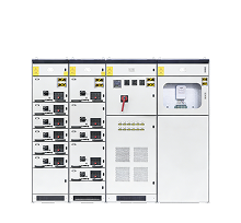
1. By Voltage Level Low-voltage switchgear: AC ≤ 1000V (e.g., GGD, GCK, GCS, MNS) High-voltage switchgear: AC > 1000V (e.g., KYN28, XGN15, GG-1A; 10kV is often classified as medium voltage) 2. By Current Type AC switchgear DC switchgear 3. By Internal Structure Fixed type switchgear Withdrawable (drawout) type switchgear 4. By Function Incoming line panels Outgoing line panels Metering panels Capacitor (compensation) panels Bus-coupler panels 5. By Structural Form Fixed structure Withdrawable structure 6. By Connection Method Welded structure Bolted (fastener) structure
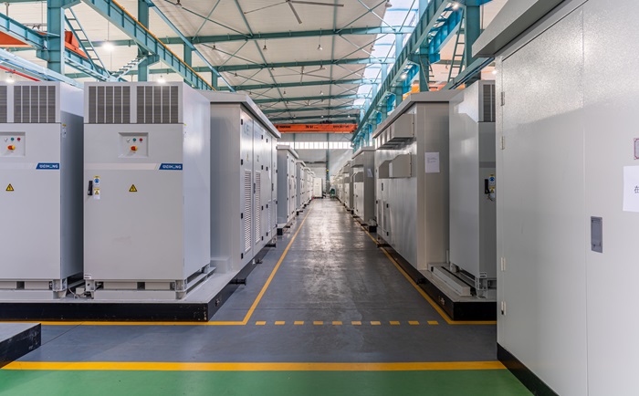
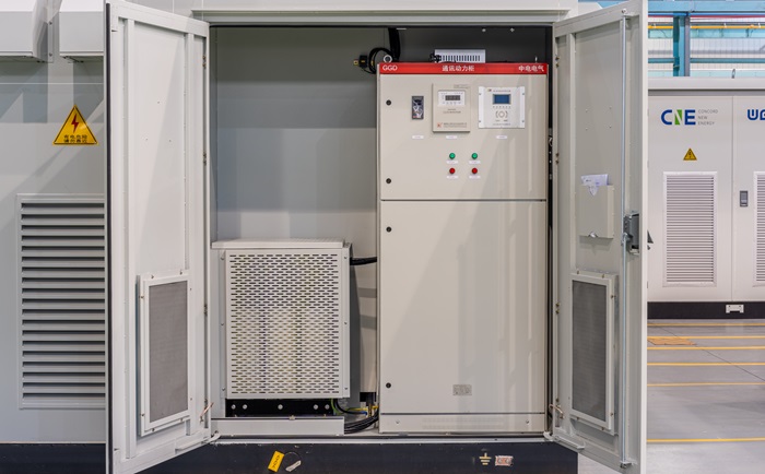
High Voltage Equipment Includes key components such as circuit breakers, disconnectors, earthing switches, load switches, fuses, CTs & VTs, surge arresters, busbars, and cable terminals. These parts can be integrated into systems like metal-enclosed switchgear, GIS, and prefabricated substations. Low Voltage Equipment Includes low-voltage switchgear, distribution boards, control cabinets, and distribution boxes, used for power distribution, control, and protection in LV systems.
1. GGD Fixed Switchgear Advantages: Simple structure, easy maintenance, strong capacity, widely used. Disadvantages: Limited expansion, large footprint, no smart system interface. 2. GCK Withdrawable Switchgear Advantages: Flexible configuration, high safety, good stability, space-saving. Disadvantages: Limited busbar protection, no advanced system integration. 3. GCS Withdrawable Switchgear Advantages: High performance, flexible design, strong reliability, good safety. Disadvantages: Higher cost. 4. MNS Modular Switchgear Advantages: Compact, modular, flexible assembly, international standard design. Disadvantages: Higher cost. 5. MCS Withdrawable Switchgear Advantages: Compact, highly configurable, supports automation and remote control. Disadvantages: High cost.
1. Efficiency performance: Pay attention to both rated efficiency and load efficiency. Standard models usually achieve over 95% efficiency, while high-performance models can exceed 97%. 2. Temperature rise and losses: Select appropriate capacity and temperature rise design to control long-term losses and ensure stable, long-life operation. 3. Environmental adaptability: Consider installation conditions such as temperature, humidity, and altitude, and choose a model suitable for the specific operating environment. 4. Economy and reliability: Evaluate purchase cost, maintenance cost, and operational reliability to ensure good cost performance and stable long-term investment return.
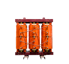
1. High hardness and difficult processing: Amorphous alloy strips are very hard and difficult to cut with conventional tools, so designs must minimize cutting and mechanical damage. 2. Thin and uneven material surface: The material is very thin and not perfectly flat, resulting in a lower core stacking factor and requiring optimized structural design to improve core density and performance. 3. Sensitive to mechanical stress: Amorphous alloy is easily damaged by stress, so the core cannot be used as a main load-bearing structure, and stress concentration must be avoided in design. 4. Annealing requirement: Core sheets must undergo annealing treatment to improve magnetic properties and reduce core losses. 5. Electrical performance optimization: Core structures are often designed with multiple independent frames to reduce cutting losses and improve magnetic balance, helping suppress harmonic effects and improve waveform quality.
1. Urban power networks: Widely used in city grids and distribution systems to reduce no-load losses and improve overall energy efficiency under fluctuating loads. 2. Residential communities: Ideal for housing areas due to low energy consumption, helping reduce electricity costs while maintaining stable power supply. 3. Industrial and commercial areas: Used in industrial parks and business districts to improve energy utilization and reduce long-term operating costs. 4. Rural and remote grids: Suitable for areas with lower and less frequent loads, improving efficiency and reducing energy loss, making them cost-effective for grid upgrades.
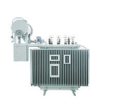
1. By Insulation & Cooling Medium Dry-Type Transformer (e.g., epoxy resin cast SCB type, H-class insulated SGB type) Oil-Immersed Transformer 2. By Core Material / Structure Silicon steel laminated core transformer Silicon steel wound core transformer Amorphous alloy core transformer 3. By Energy Efficiency Standard SJ, S7, S9, S11, S13, S15 series (higher series indicates better energy efficiency) 4. By Phase Type Single-phase transformer Three-phase transformer 5. By Capacity (kVA Rating) Common standardized ratings include: 50, 80, 100, 125, 160, 200, 250, 315, 400, 500, 630, 800, 1000, 1250, 1600, 2000, 2500, 3150, 4000, and 5000 kVA, following standard R10 preferred series values.
Function: In photovoltaic power systems, a PV step-up transformer plays a key role in power conversion and grid integration. It converts the generated electricity into a grid-compatible form, increases voltage for efficient transmission, and provides electrical isolation. It also helps stabilize power quality and protects PV equipment from grid voltage fluctuations, ensuring safe and reliable system operation. Applications: PV step-up transformers are widely used in solar power systems of different scales: Residential PV systems: Support grid connection and allow users to consume solar power and export surplus energy. Commercial PV systems: Help businesses reduce electricity costs and improve energy efficiency. Utility-scale solar plants: Essential equipment for large photovoltaic power stations, enabling stable transmission and supporting clean energy transition.
1. Power (Generation) Transformers: Used in power plants to step up voltage for long-distance transmission. They are typically high-capacity and high-voltage units. 2. Transmission Transformers: Installed in transmission systems to transfer electricity over long distances between generation and distribution networks, reducing energy loss through high-voltage operation. 3. Distribution Transformers: Used in urban and rural distribution networks to step down high voltage to usable levels for residential, commercial, and industrial users. This is the most common type in box substations. 4. Special-Purpose Transformers: Custom-designed for specific industrial applications such as metallurgy, electric furnaces, and welding systems, with tailored performance and operating requirements.
1 - Strong Overload Capability: Capable of continuous operation at 2× load for 2 hours or 1.6× load for 7 hours without affecting service life. 2 - Convenient High-Voltage Connection System: Uses elbow-type plug-in connectors to simplify cable installation and support live operation as a load switch. 3 - Dual Fuse Protection System: Includes BAY-o-net and ELSP fuses for coordinated protection of secondary and primary sides. 4 - High Flash Point Insulating Oil: Uses FR3 high flash point oil to improve fire safety performance. 5 - Integrated Design: All key components are integrated in a single tank for compact structure and easy maintenance.